Imagine a small clay elephant on your desk. You can photograph it, but a photograph fixes the viewpoint. A digital 3D version lets someone turn it around, inspect its ears, place it in a virtual room, or prepare a physical copy.
Making that version requires more than collecting attractive pictures. Software needs evidence about where surfaces are, how different observations fit together, and what those surfaces look like. Different capture methods answer those questions in different ways.
The first useful distinction is between a representation that looks convincing and one whose geometry is suitable for a particular job. A beautiful rotating preview, a model for a game, and a model for dimensional inspection have different requirements.
What a 3D scan actually contains
Several related data types can appear during reconstruction. They should not be treated as interchangeable.
| Representation | What it contains | What it contributes |
|---|---|---|
| Point cloud | Samples with 3D coordinates, sometimes colour or other attributes | Evidence about locations on visible surfaces |
| Mesh | Vertices joined into faces, often triangles | A connected surface representation |
| Texture map | An image mapped onto a surface using coordinates | Colour and visible surface appearance |
A point cloud can resemble an object without specifying how neighbouring points connect. Surface reconstruction adds that connectivity to create a mesh. Open3D, for example, documents several reconstruction methods rather than one universal way to join the dots. 3
A texture supplies appearance without necessarily adding geometry. Painted wrinkles can look detailed even when the underlying surface is smooth. This is why switching off the colour texture is such a useful inspection step: it reveals what the shape itself contains.
Photogrammetry starts with overlapping views
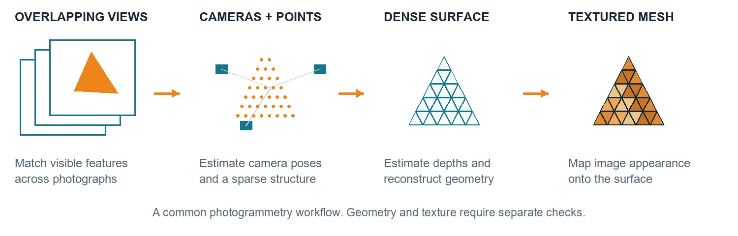
Photogrammetry extracts measurements and structure from photographs. In a common reconstruction workflow, you move around the stationary elephant and capture overlapping views. As your viewpoint changes, nearby and distant features shift differently within the images. Those changes provide evidence about depth.
Finding the cameras and a sparse structure
Structure from Motion, usually shortened to SfM, estimates camera positions and orientations alongside a set of 3D points. Software finds distinctive image features, proposes matches across photographs, and checks whether those matches agree with plausible geometry. 1
A mark beside the elephant's eye might appear in several photos. Once its observations and the camera geometry are sufficiently constrained, triangulation estimates its 3D position. Repeating this creates a sparse reconstruction: a scaffold of points, not yet a complete surface.
The estimates are refined together through bundle adjustment, which reduces the mismatch between observed image features and where the reconstructed points project into those images. Camera calibration, including lens behaviour, is part of obtaining consistent geometry. 1
Simply standing still and turning the camera mainly changes what is framed. For useful depth evidence, capture positions should also change, while retaining substantial overlap between neighbouring views. 2
Recovering more of the surface
Multi-View Stereo, or MVS, uses the estimated cameras to infer denser depth information from multiple views. Depth maps can then be fused into a dense point cloud, followed by surface reconstruction. These are related but distinct stages; camera alignment does not mean the object has already been fully modelled. 2
Texturing projects suitable photographs onto the mesh. UV coordinates connect locations on its surface to locations in a texture image, often arranged as an atlas of surface regions. Combining several views can introduce seams or inconsistent brightness if their appearance differs. 2
The digital elephant now has both a shape and a photographed appearance. Missing evidence can still leave holes, distorted ears, or an underside that was never captured.
Depth scanners add their own light
Photogrammetry can work with ordinary photographs. Active depth systems illuminate the scene to help measure its structure.
LiDAR measures range
LiDAR uses laser light for ranging. In a common time-of-flight design, the instrument emits a pulse and measures how long its reflection takes to return. Distance is obtained from the travel time and light's speed, with the round trip accounted for. Combining ranges with measurement directions produces 3D samples. 4
Repeated measurements build a point cloud. Captures from different scanner positions must also be placed in a common coordinate system. A device may combine range measurements with camera images or motion tracking, so an app's final model can depend on more than its depth sensor alone.
Structured light measures a projected pattern
A structured-light scanner projects known patterns, such as stripes, onto the object. Cameras observe how those patterns appear across its surface. With calibrated projector and camera geometry, triangulation recovers surface positions. This differs from measuring a pulse's travel time. 5
The projected pattern can provide information where natural surface markings are scarce. However, active illumination does not eliminate every difficult material or hidden region. Range, ambient light, surface properties, calibration, and viewing geometry still matter. Laser-line triangulation is another approach, so “laser scanner” does not always mean time-of-flight LiDAR. 5
Some surfaces hide their shape from the camera
A matte, patterned object is often easier to reconstruct photographically than a featureless white one. Distinctive markings help establish correspondences; a broad blank area provides fewer reliable matches. Reflective surfaces introduce another problem: a highlight can move when the camera moves, even though the object stays still. 11
Transparent material can show the background or refract light instead of presenting an unambiguous visible surface. Structured-light systems can also struggle when projected light passes through, scatters within, or reflects away from the object. Deep recesses cause problems when illumination or a camera cannot reach them. 6
For the elephant, the gap beneath an ear may be missing even when the ear looks complete from the front. More pictures from essentially the same angle will not expose that hidden region. Different viewpoints are needed.
These limitations also explain why an automatic repair deserves scrutiny. Filling an unseen base may make a model convenient to display, but that new surface is an estimate rather than a direct observation.
Correct shape needs a scale and an accuracy check
An image-only reconstruction without a metric reference generally has no uniquely determined physical scale. A small object photographed nearby can produce the same image geometry as a larger version photographed from proportionally farther away.
A known distance supplies the missing scale. Photogrammetry software can use scale bars or identifiable points with a measured separation. If a 100 mm reference measures 2 model units, the scale factor is 100 ÷ 2 = 50 mm per model unit. 7
This fixes the conversion of units; it does not remove every local distortion. Include additional known distances as checks rather than using every reference to fit the model. Agreement at one location does not establish accuracy everywhere. 7
Depth scanners usually provide metric ranges, but their outputs still have measurement uncertainty. Resolution describes the detail represented; accuracy concerns agreement with the actual object. A very dense mesh can preserve a systematic measurement error with impressive detail. Manufacturer terminology and test conditions deserve attention when interpreting a specification. 8
For a desk ornament, a visual inspection may be sufficient. For a replacement component that must fit another part, check the relevant dimensions and the full measurement workflow. A textured scan also does not automatically become an editable CAD model with meaningful holes, planes, and design parameters.
NeRFs and Gaussian splats represent appearance differently
Not every convincing 3D capture is a textured mesh.
A Neural Radiance Field, or NeRF, represents a scene using a function that relates spatial position and viewing direction to density and colour. The original method optimises a neural network from photographs with known camera poses, then renders new viewpoints by sampling along camera rays. 9
That makes view-dependent appearance part of the representation. A shiny surface can look different from different directions without having to be described by one fixed photograph painted onto a mesh. A NeRF can support geometry extraction, but producing and validating a surface is an additional step. 9
The original 3D Gaussian Splatting method represents the scene with many overlapping 3D Gaussian elements. These have properties including position, shape, opacity, and appearance. Optimisation adjusts them so that rendered views match the input photographs, and a splatting renderer projects them into images. 10
These elements are not a conventional set of connected surface triangles. A compelling NeRF or splat therefore does not automatically provide watertight geometry for printing, dependable collision surfaces, or verified dimensions. Those uses require suitable conversion and checks. The right output depends on whether you need to view the object, interact with its surface, or measure it.
A practical capture workflow
Start with a modest goal: make a viewable model of a rigid, matte object with visible markings. The clay elephant is a better first experiment than a polished spoon or a clear glass. Decide whether you need only appearance or also meaningful scale.
Use steady, diffuse illumination and keep the object still. Capture a circuit of overlapping photographs, then additional circuits from higher and lower angles. Keep the object sharp and large enough in the frame to preserve detail. Inspect the photographs before moving on; blur cannot be repaired simply by requesting a denser reconstruction. 11
For a simple first capture, walking around the object avoids the extra complication of a moving object against a stationary background. If an underside requires repositioning, treat it as a separate capture that must be aligned using shared visible features.
After processing, inspect camera alignment and the point cloud before judging the finished texture. Look for disconnected pieces, doubled surfaces, thin parts that have vanished, and implausible bridges across gaps. Revisit missing coverage when possible.
Clean the mesh with its intended use in mind. Surface reconstruction and hole filling can create geometry beyond the measured samples; Open3D explicitly illustrates this behaviour in Poisson reconstruction. Smooth shading should not be mistaken for evidence that those surfaces were captured. 3
Finally, check scale if needed, inspect the untextured geometry, and test the exported model in its destination application. Preserve the original photographs or scans alongside the processed result. That leaves you a route back when an attractive preview conceals a problem.
A useful digital replica emerges from capture, reconstruction, and validation together. Each contributes something different: observations of the object, an interpretation of those observations, and evidence that the result is fit for its purpose.
Sources and further reading
Specifications, research papers and official documentation support the technical explanations. The examples and diagrams are original editorial material. Research checked on 23 October 2026.
- Structure-from-Motion Revisited — Original COLMAP research describing feature correspondence, camera estimation, triangulation, and bundle adjustment.
- COLMAP Tutorial — Official explanation of overlapping views, sparse reconstruction, multi-view stereo, surface reconstruction, and texture mapping.
- Open3D Surface Reconstruction — Official examples of converting point clouds into meshes and identifying surfaces extrapolated beyond reliable observations.
- What Is LiDAR — Manufacturer explanation of pulsed laser ranging through emission, reflection, and time-of-flight measurement.
- Triangulation in Metrology — ZEISS explanation of calibrated structured-light projection and laser triangulation, including practical limitations.
- How Does Structured-Light 3D Scanning Work — Artec explanation of structured-light capture and difficulties involving transparent, reflective, and recessed surfaces.
- Creating Scale Bars Without Coded Targets — Agisoft guidance on supplying measured distances, scaling models, and using independent check scale bars.
- Understanding Portable 3D Scanning Technologies — Creaform technical guide distinguishing accuracy, resolution, repeatability, and scanner positioning considerations.
- NeRF Representing Scenes as Neural Radiance Fields for View Synthesis — Original project explanation of neural density and appearance fields, novel-view rendering, and optional mesh extraction.
- 3D Gaussian Splatting for Real-Time Radiance Field Rendering — Original research describing Gaussian scene representations, optimisation, and splatting-based novel-view rendering.
- General Image Capture Tips — Agisoft recommendations on image sharpness, lighting, coverage, surface texture, and capture quality.